
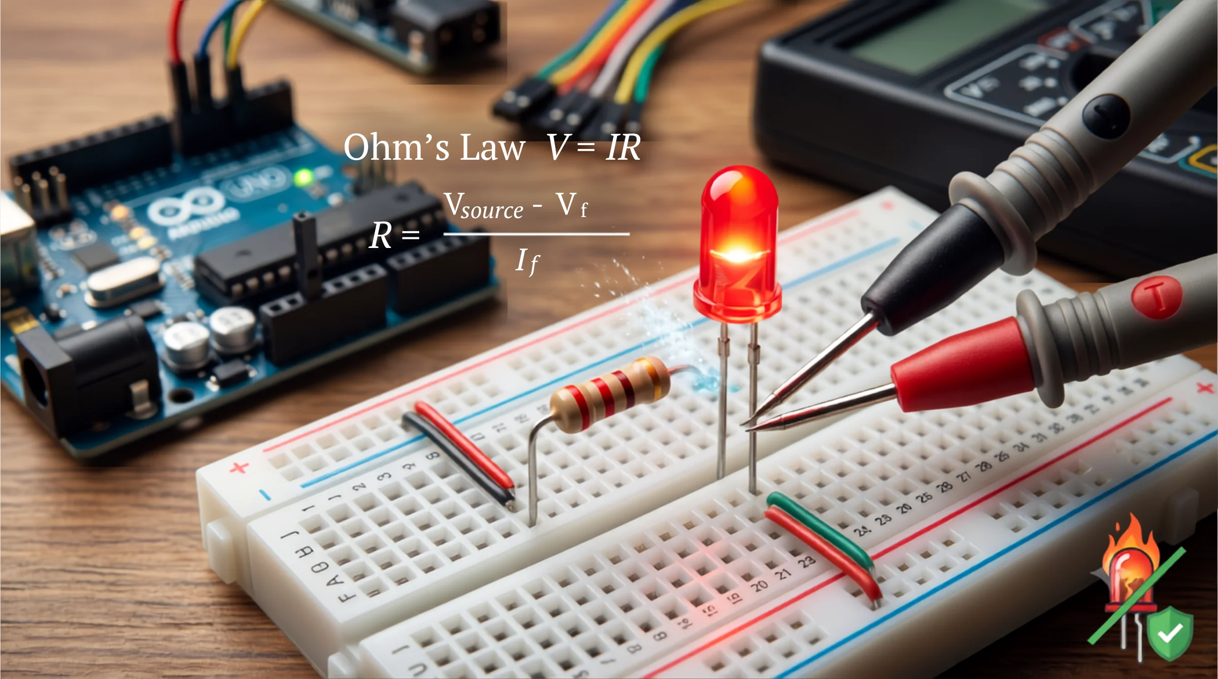
Ever plugged an LED directly into your Arduino or a 9V battery, only to watch it flash blindingly bright for a fraction of a second before dying forever? That faint whiff of burnt plastic is a rite of passage for every maker. But running through a bag of micro-components shouldn’t be the cost of entry for your DIY electronics journey.
The culprit isn’t a defective batch of LEDs. It’s an unrestrained flood of electrical current tearing through a delicate semiconductor junction. Let’s fix that—permanently.
The Physics Behind It: Why LEDs Need a Current-Limiting Resistor
Unlike traditional incandescent bulbs, which naturally resist electrical flow through a heating filament, a Light Emitting Diode (LED) is a semiconductor device. It behaves as a non-linear load with a property known as negative dynamic resistance.
The Semiconductor Cascade
When you apply a voltage that exceeds the LED’s Forward Voltage ($V_f$), the internal P-N junction opens the floodgates. Beyond this threshold, even a microscopic increase in supply voltage leads to an exponential surge in current ($I$).
$$\Delta V \implies \uparrow\uparrow I$$
Without a component in the circuit to choke this flow, the current rapidly exceeds the LED’s Maximum Forward Current ($I_f$)—typically around $20\text{ mA}$ ($0.02\text{ A}$).
Thermal Runaway in Micro-Seconds
This runaway current creates instant internal heating ($P = I^2 R$). As the semiconductor junction heats up, its resistance drops even further, drawing more current. Within milliseconds, this thermal runaway vaporizes the microscopic bond wire connecting the semiconductor die, rendering your LED permanently dead.
To prevent this catastrophic failure, we place a current-limiting resistor in series with the LED. The resistor absorbs the excess voltage from your power supply and establishes a safe, fixed operating current based on Ohm’s Law:
$$V = I \times R \implies R = \frac{V_{source} – V_f}{I_f}$$
Interactive Tool Placeholder
LED Resistor Calculator
Adjust sliders to calculate resistor & power rating
Step-by-Step Troubleshooting: Calculating Your Resistor Value
Follow this bulletproof 3-step process to size your current-limiting resistor perfectly every time.
Step 1: Identify Your Hardware Specs
Check your LED datasheet or use the quick reference table below to find your component’s typical operating parameters:
| LED Color | Typical Forward Voltage (Vf) | Standard Current (If) |
| Red / Orange | $1.8\text{ V} – 2.1\text{ V}$ | $20\text{ mA}\ (0.02\text{ A})$ |
| Yellow / Green | $2.0\text{ V} – 2.2\text{ V}$ | $20\text{ mA}\ (0.02\text{ A})$ |
| Blue / White / UV | $3.0\text{ V} – 3.4\text{ V}$ | $20\text{ mA}\ (0.02\text{ A})$ |
Step 2: Run the Ohm’s Law Formula
Subtract the LED’s forward voltage ($V_f$) from your source voltage ($V_{source}$) to find the voltage drop required across the resistor. Then, divide that number by your target forward current ($I_f$).
- Example Project: Running a Red LED ($V_f = 2.0\text{ V}$, $I_f = 20\text{ mA}$) on a $5\text{V}$ Arduino pin ($V_{source} = 5\text{ V}$).
$$R = \frac{5\text{ V} – 2.0\text{ V}}{0.02\text{ A}} = \frac{3.0\text{ V}}{0.02\text{ A}} = 150\,\Omega$$
Step 3: Round Up and Check Power Dissipation
- Select Standard Resistors: You might not find an exact $150\,\Omega$ resistor in your kit. Always round UP to the nearest standard value (e.g., $220\,\Omega$). A slightly higher resistance safely dims the LED without risking burnout; rounding down increases thermal stress.
- Verify Wattage Rating: Calculate power dissipation ($P = I^2 R$). For our example:$$P = (0.02\text{ A})^2 \times 150\,\Omega = 0.06\text{ W}$$Standard $1/4\text{ Watt}$ ($0.25\text{ W}$) resistors will comfortably handle this load without overheating.
Circuit Protection Best Practices
When building permanent custom PCBs or prototyping complex breadboard circuits, never share a single limiting resistor across multiple parallel LEDs. Minor manufacturing variations in forward voltage will cause one LED to draw more current than the rest—triggering a chain reaction where each LED overheats and fails sequentially. Always assign a dedicated resistor to each LED branch to guarantee long-term circuit stability.
To build a stronger foundation in electronics and maker physics, browse our [Gear & Logic: Applied Physics and Mathematics] hub, or access other design simulators in [Interactive Tools: Live Science & Engineering Calculators].