
Stop Blaming Your ISP: Fix Dead Zones Using the Inverse-Square Law
Is your Wi-Fi dropping the second you step into your bedroom? You bought a high-speed router, yet streaming a basic 1080p video in the back room feels like using dial-up. Before you waste money upgrading your internet plan, you need to understand that the issue isn’t your provider—it’s basic wave physics.
Why Signal Drops: The Wave Physics Behind Dead Zones
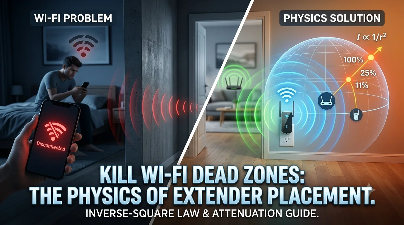
When a router broadcasts a Wi-Fi signal, it radiates radio frequency (RF) energy outward in an expanding sphere. The energy total stays constant, but as that sphere grows, the energy spreads thinner over a wider surface area.
The Inverse-Square Law Explained
Wi-Fi signals operate under the Inverse-Square Law ($I \propto \frac{1}{r^2}$). Double your distance ($r$) from the router, and the signal strength ($I$) doesn’t drop by half—it drops to one-quarter ($1/2^2$) of its original intensity. Triple the distance, and you get one-ninth ($1/3^2$).
$$\text{Signal Intensity} \propto \frac{1}{\text{Distance}^2}$$
Wall Attenuation: Density vs. Wave Propagation
Distance isn’t the only obstacle. When electromagnetic waves pass through physical materials, they lose power through absorption and reflection.
- 2.4 GHz vs. 5 GHz: 5 GHz offers higher throughput but shorter wavelengths that struggle to penetrate dense obstacles. 2.4 GHz features longer wavelengths that pass through solid objects better, but offer lower top speeds.
- Material Density: Drywall absorbs minimal energy, while reinforced concrete and metals act like signal sinks.
Signal Loss (Attenuation) by Obstacle Type
| Obstacle Material | Signal Loss Range (dBm) | Effective Impact |
| Drywall / Clear Glass | $-1 \text{ to } -3 \text{ dBm}$ | Minimal reduction |
| Solid Wood Door | $-3 \text{ to } -5 \text{ dBm}$ | Noticeable speed drop |
| Brick Wall | $-6 \text{ to } -10 \text{ dBm}$ | Significant latency increase |
| Reinforced Concrete / Metal Frame | $-10 \text{ to } -18 \text{ dBm}$ | High risk of packet loss/disconnection |
| Mirrors / Water Tanks | $-8 \text{ to } -12 \text{ dBm}$ | Severe RF reflection |
Interactive Wi-Fi Extender Placement Calculator
[Insert JavaScript Extender Placement & Attenuation Calculator Here]
3-Step Placement Strategy for Wi-Fi Extenders
Placing a Wi-Fi extender inside your dead zone is the most common mistake. If the extender receives a weak signal, it will simply repeat a weak, unreliable connection.
Step 1: Map the “Sweet Spot” (The 50/50 Distance Rule)
Position the extender halfway between your main router and the dead zone. The extender must sit well within the router’s strong transmission bubble (ideally receiving at least $-60 \text{ dBm}$ or 3 out of 4 Wi-Fi bars) so it has a clean signal to relay.
Step 2: Establish Direct Line-of-Sight Around Structural Barriers
Avoid placing the extender behind concrete pillars, large metal appliances, or mirrors.
- Position the device in an open hallway or near an open doorway.
- Angle the extender so waves can bypass thick walls rather than passing through them diagonally, which artificially increases the barrier’s effective thickness.
Step 3: Optimize Vertical Placement and Antenna Polarization
RF energy drops significantly near floor level due to carpet absorption and furniture blockage.
- Height: Mount or plug in the extender at desk level or higher (around $1 \text{ to } 1.5 \text{ meters}$).
- Antennas: If your device has external antennas, position one vertically (for optimal horizontal coverage across rooms) and one horizontally (to push signal through multi-story layouts).
Technical Recommendations for High-Throughput Environments
While Wi-Fi extenders offer a cost-effective solution for basic dead zones, they inherently halve available bandwidth because they communicate bidirectionally on the same channel. For heavy bandwidth demands—such as 4K streaming, low-latency gaming, or multi-device remote work—consider upgrading to a Mesh Wi-Fi system with dedicated wireless backhaul or running an Ethernet cable to a dedicated Access Point (AP). Evaluating your physical floor plan against RF attenuation dynamics ensures long-term network stability without unnecessary hardware expenditure.
For more technical guides on signal attenuation and wave dynamics, visit our [Gear & Logic: Applied Physics and Mathematics] archive, or map your home grid in [Interactive Tools: Live Science & Engineering Calculators].