
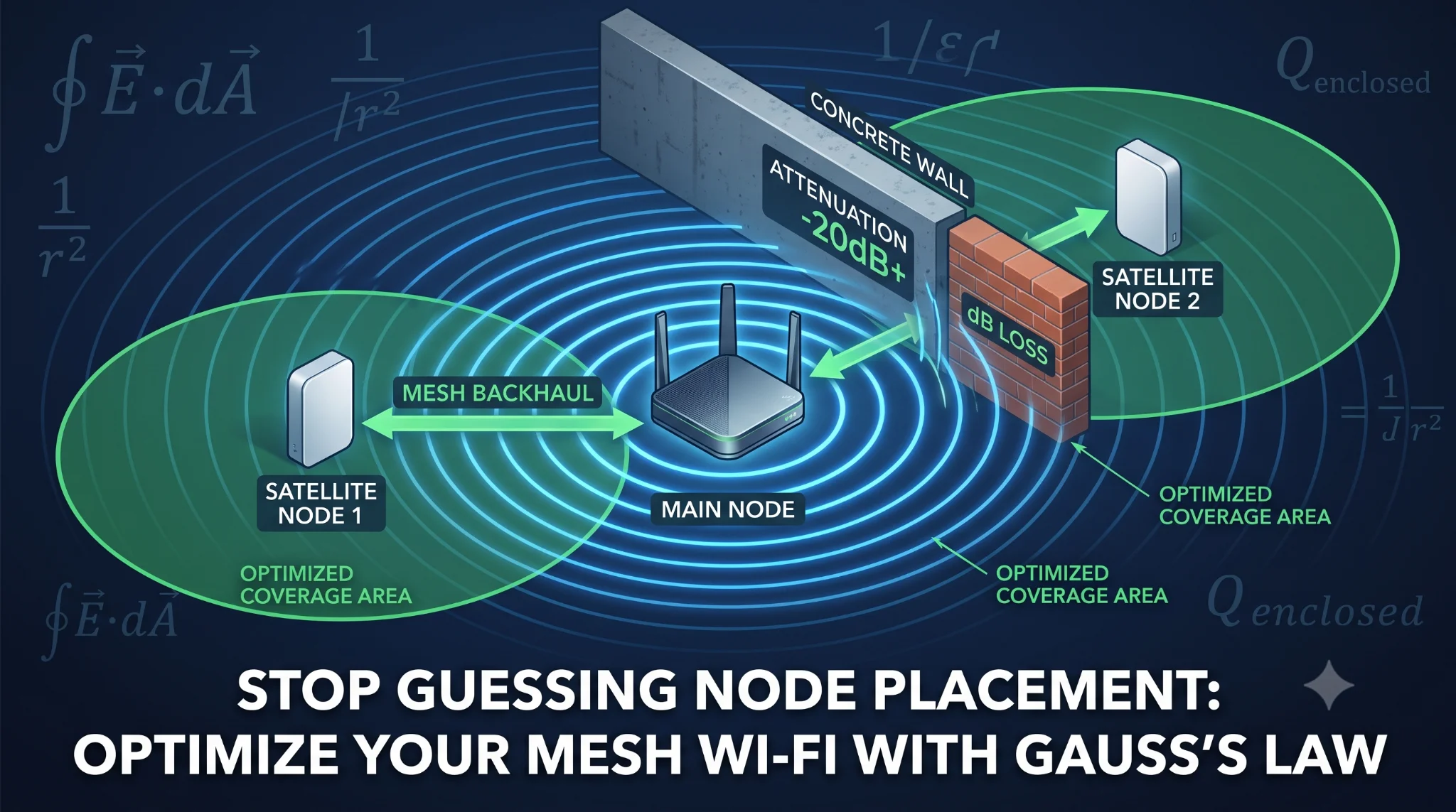
Is your gigabit internet crawling at 5 Mbps the moment you step into the master bedroom or home office? You bought an expensive multi-pack mesh system, dropped nodes in every room, yet Zoom calls drop and 4K streams keep buffering.
The frustrating truth? Adding more nodes often makes your Wi-Fi worse. You don’t need more hardware—you need to align your network layout with fundamental electromagnetic field physics.
The Physics Behind Dead Zones: Gauss’s Law & Attenuation
To fix signal drop-off, you must understand how Radio Frequency (RF) energy travels through a three-dimensional space. RF propagation boils down to two key physics principles: the Inverse-Square Law and Gauss’s Law for Electricity.
$$\Phi_E = \oint \mathbf{E} \cdot d\mathbf{A} = \frac{Q_{\text{enclosed}}}{\varepsilon_0}$$
Understanding Flux Density and Signal Loss
Think of your Wi-Fi router’s omnidirectional antenna as a point source radiating electromagnetic energy outward in an expanding sphere.
- Gauss’s Law states that the total electric flux ($\Phi_E$) passing through any closed surface is proportional to the enclosed charge ($Q_{\text{enclosed}}$).
- As the imaginary sphere around your router expands, the fixed power output (measured in milliwatts) spreads over a larger surface area ($A = 4\pi r^2$).
This spatial distribution means signal intensity drops exponentially with distance according to an inverse-square relationship, long before it hits a physical barrier.
Physical Obstacles and Material Attenuation
When this expanding electromagnetic wave collides with matter—like drywall, glass, or steel-reinforced concrete—the electric field interacts with the material’s atomic structure. Dielectric absorption and reflection instantly rob the wave of kinetic energy.
The table below outlines how common home materials degrade your $2.4\text{ GHz}$ and $5\text{ GHz}$ RF signals:
| Construction Material | 2.4 GHz Attenuation Loss | 5 GHz Attenuation Loss | Signal Impact Level |
| Clear Glass / Wood Door | $-1\text{ dB} \sim -2\text{ dB}$ | $-2\text{ dB} \sim -4\text{ dB}$ | Negligible |
| Drywall / Plasterboard | $-2\text{ dB} \sim -3\text{ dB}$ | $-4\text{ dB} \sim -6\text{ dB}$ | Low |
| Solid Brick / Ceramic Tile | $-6\text{ dB} \sim -8\text{ dB}$ | $-10\text{ dB} \sim -14\text{ dB}$ | Moderate-High |
| Reinforced Concrete Wall | $-10\text{ dB} \sim -18\text{ dB}$ | $-20\text{ dB} \sim -30\text{ dB}+$ | Severe (Dead Zone) |
| Mirrors / Metal Sheets | $-12\text{ dB} \sim -15\text{ dB}$ | $-20\text{ dB} \sim -28\text{ dB}$ | Reflection / Deflection |
Note: A $3\text{ dB}$ drop cuts your signal strength in half. A $-30\text{ dB}$ loss from a concrete wall reduces the original wave power to $0.1\%$.
Interactive Tool Placeholder
Wi-Fi Signal Coverage Simulator
Estimate signal loss and determine mesh expansion needs
Loading simulation…
Step-by-Step Troubleshooting: Golden Placement Strategy
Stop placing satellite nodes directly inside dead zones. If a node receives a weak signal from the main router, it can only re-transmit that same degraded, high-latency connection.
Follow this 3-step physical optimization strategy:
1. Establish the “Line-of-Sight Buffer Zone” (The 50% Overlap Rule)
Place secondary nodes roughly halfway between the main router and the physical dead zone.
- Target a Received Signal Strength Indicator (RSSI) of $-60\text{ dBm}$ to $-65\text{ dBm}$ at the satellite node location.
- Use a mobile Wi-Fi analyzer app to measure signal strength before anchoring the unit. If the main router signal dips below $-70\text{ dBm}$, move the node closer.
2. Elevate and Isolate (Clearing Fresnel Zones)
Wi-Fi waves radiate down and outward in an elliptical pattern known as the Fresnel Zone.
- Elevate Nodes: Place devices at head height ($1.5\text{m} \sim 1.8\text{m}$) on open shelves rather than floor level or inside TV cabinets.
- Maintain Clearance: Keep nodes at least $1\text{m}$ away from metal appliances, large mirrors, and dense electrical wiring that cause destructive wave interference.
3. Leverage Ethernet Backhaul for High-Density Barriers
When facing thick load-bearing concrete or structural brick walls, pure wireless daisy-chaining fails due to extreme attenuation losses exceeding $-20\text{ dB}$.
- Run a dedicated Cat6/Cat6e Ethernet cable from the main router through the barrier directly into the remote node’s WAN/LAN port.
- Offloading the backhaul traffic to a physical wire frees up $100\%$ of the node’s wireless spectrum for client devices, delivering maximum throughput with minimal latency.
Conclusion & CTA
Eliminating Wi-Fi dead zones isn’t about trial and error or buying extra hardware—it’s about respecting electromagnetic physics. By mapping out structural barriers, maintaining line-of-sight buffer zones, and deploying wired backhauls across high-attenuation walls, you transform an unpredictable wireless setup into a high-performance network. Optimize your node placement using RF attenuation values, and enjoy seamless, zero-lag connectivity across every square inch of your space.
If this guide helped you optimize your home network, share it with anyone struggling with frustrating Wi-Fi dead zones!
Unlock the mathematical equations of signal propagation in our [Gear & Logic: Applied Physics and Mathematics] section, or optimize your home layout using the tools in [Interactive Tools: Live Science & Engineering Calculators].